Making board cutouts
For projects one and two, we get you to add a mechanical one layer to a prexisting board outline. This method is fine for the other two, but for the altium test you will need to actually define the board edge yourself.
We showed you how to do this in one of the first few labs, but its been a while so here is a quick guide.
Defining a board outline
Imagine we want to make an 8cm x 8cm board with a 0.80 mm cutting tool diameter.
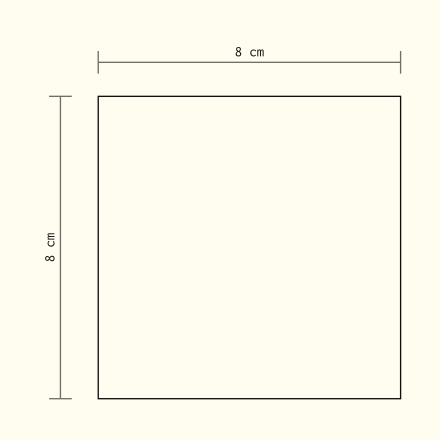
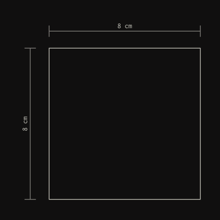
Step One: Defining the Board Shape
First, we create a rectangle the intended shape and size on the Keep Out layer.
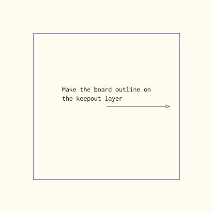
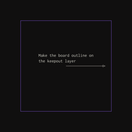
Select it, and use Design -> Board Shape -> Define Board Shape from Selected Objects
This will define the shape of the board.
Step Two: Adding a mechanical One Line
Select Mechanical 1 and create a line on the board edge
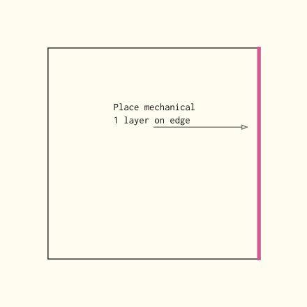
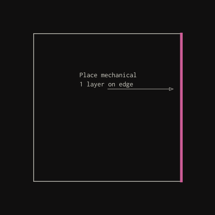
Repeat this for all edges of the board.
Step Three: Set Mechanical 1 lines to Correct Thickness
Select all of your Mechanical 1 lines, open Properties 1, and set “Width” to whatever the diameter of your cutting tool is (in this case, 0.80mm).
1 You can do this quickly by pressing F11! See here for more keyboard shortcuts.
Step Four: Move out from edge
For each of your new Mechanical 1 lines you just made, you will need to move them out so that the interior edge of this line is where you want to cut.
i.e. you need to go from this:
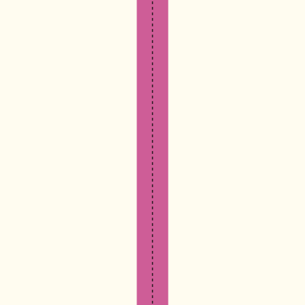

To this:
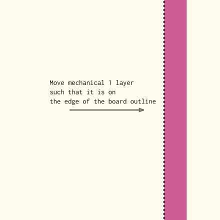
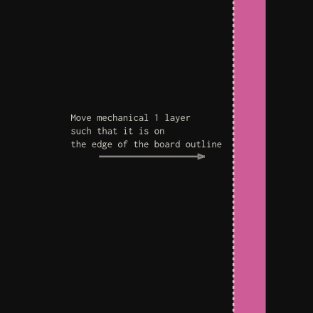
I would recommend doing this by modifying the coordinates. If you select the line and open Properties, you can change either both the start and end x or y coordinates by half the cutting tool diameter.
In the example diagram I showed you, I need to move it right by 0.4mm. So I will add 0.4mm to the x coordinates.
You can either do the math for that in your head, or you can literally add +0.4mm to the x coordinate boxes. 2
2 So if it was originally like 1000mil you would change it to 1000+0.4mm and it will automatically update to 1,015.74mil
If it was on the top of bottom of the board you would add or subtract 0.4mm to the y coordinates instead.
Step Five: Extending the Lines
Once you have done that, it will look like this:
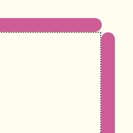
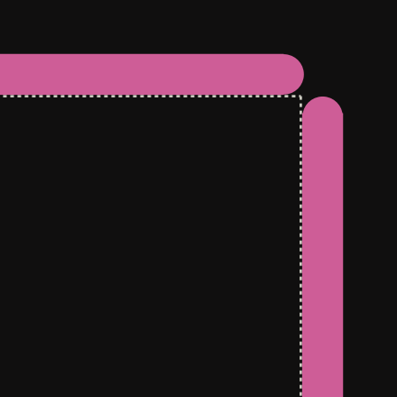
You can connect these together by modifying the other coordinates, or you can click and drag the ends togther.
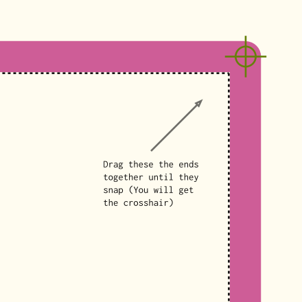
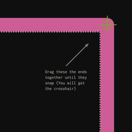
Now you are done.